
![]()
![]()
![]()
![]()
Note:
November 10, 2023
This is my attempt of archiving the cHipp toggle Web page, which went unexpected and suddenly off-line on November 10. The original link (no longer works) was from here:
http://www.rogerj.co.uk/clock.htm
Roger has graciously permitted me to present his project here on this web site.
![]()
The cHipp Toggle clock
A DIY, free pendulum, electrical master clock project.

Inspired by Matthias Hipp's idea
of 1842.

![]()
First...some info on the Hipp Toggle.
Matthias Hipp's original Hipp toggle was a simple metal toggle attached the the side of the pendulum rod that closed a contact when the arc of swing fell to a certain minimum amplitude. It then momentarily powered an electro magnet as the Pendulum passed through "zero" or bottom dead centre. This impulse accelerated the pendulum slightly on that swing. The arc increased and the Hipp toggle effect would not be invoked again until the arc had again fallen to the set amplitude.
The clever bit is that the pendulum is subjected to the minimum of interference over significant time intervals - often 30 seconds or more.
![]()
Matthias Hipp proposed this idea in 1842. Below is Frank Hope-Jones description of the Hipp toggle. It's reproduced from his 1949 book "Electrical Timekeeping". Frank Hope-Jones was the designer and manufacturer of the 20th century Synchronome master clocks (which did not utilise the Hipp toggle)
![]()
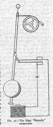 |
....But one cannot speak of merit in electric clock inventions without giving pride of place to the Hipp "Butterfly" escapement which is illustrated in fig. 37. An apparently free /pendulum has an armature attached to its lower end above an electro-magnet fixed to the case. The pendulum carries a little freely swinging vane. This vane trails backwards and forwards over a notched block mounted on the end of the upper spring of a pair of contact springs until, as a result of the gradually decreasing arc, it engages the notch and forces the top spring vigorously into contact with the lower. The notched block, or the electro magnet, is placed a little off-centre, and the contact is so adjusted that the attraction takes place at the correct phase of the pendulum's vibration, the optimum position for increasing the arc and causing the vane to trail over and beyond the notch until the action is called upon to repeat itself. Also: Observe that,
though fluctuations of battery power vary the value of the
impulse, nevertheless the frequency of the impulses is
increased automatically and in exact proportion to their
lack of strength; hence the average arc is reasonably
constant. You must read Frank Hope-Jones's interesting book
for more. |
![]()
The Hipp Toggle principal was not widely used but the British Post Office used it in their telephone exchange master clocks until as late as 1980. There is a good explanation of the Hipp Toggle Post Office No. 36 clock at
http://www.hvtesla.com/masters/po36_toggle.html
![]()
The cHipp clock
This project may interest you if you are
interested in electric clocks and you have a basic understanding of
logic IC's at the hobbyist level. My mechanical skills are not great
so the mechanical construction I used may seem basic. My inspiration
came from the master clocks with one second pendulums that were so
popular in large buildings during the first three quarters of the
20th century. The Synchronome clock designed by Frank Hope-Jones
being one of the best.
The time keeping of the Synchronome clocks - claimed to be
within 2 seconds per week - would be the standard I would aim to
achieve - or perhaps better..
Almost everything I know about clocks has come from the book referred to above. I have tried to abide by the important principles outlined by Hope Jones. in that book. There are other electrically maintained pendulum clock ideas to be found on the internet and no claim is made that this scheme is any better than the others. It is just an interesting experiment in basic electronics and horology.
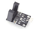
The "toggle" effect is effected with opto-interupters, rather than mechanical devices. These have an infra-red beam passing between two small pillars, which, when broken by a passing object, output a pulse for as long as the beam is broken. The type I have used have a comparator chip on a small PCB and were sourced cheaply from eBay. (as low as 99p)
A short length of soft sleeving which I will call the "flag" is attached beneath the bob so that it passed between the the pillars of three opto-interupters as the pendulum swings back and forth, creating the operating pulses as it passes. Soft plastic sleeving is used to prevent damage if the flag accidentally hits the arms of the opto-interupter.
The optos are arranged from right to left in the order A, B, C. When the pendulum is stationary the flag hangs midway between optos A and B - ie. at Bottom Dead Centre (BDC). An important point is that the electro magnets are co-incident with opto A; slightly to the right of BDC.
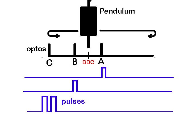
When the clock is running, as the pendulum swings from its rightmost extremity, it first passes through opto A, then B generating a short pulse from each one as it goes. A and B and C are all 0.5" apart A and B are centralised on BDC.
Opto C is the Hipp Toggle sensor. It works like this. Assume the pendulum has sufficient amplitude to swing right through opto C at its leftward extremity. A pulse is generated. It then stops and begins to swing back to the right. It passes through C again, generating a second pulse.
So on every swing that has sufficient
amplitude to pass through opto C twice, two pulses are generated in
quick succession. These are fed to a CMOS flip-flop (ff) chip (CD4013, a)
which is wired to divide by two. In other words, the output of the
4013 ff is clocked HIGH then LOW.
This is the digital equivalent of the toggle
in the mechanical version passing over the V block.
All the while the pendulum arc is slowly decreasing and eventually there will come a time when the flag does not pass right through opto C, but enters it, reverses, and proceeds to the right again generating only ONE pulse. This will clock the counter HIGH and and it will remain HIGH as returns to the right. This is the equivalent of the mechanical toggle catching on the V block in a mechanical Hipp Toggle clock.
As the pendulum continues its swing back to
the right it arrives at opto B (1/4" from BDC) generating another
pulse. A basic chip known as a NAND GATE (IC3a, CD4011) detects that
it now has two HIGH signals on its input
terminals - one from opto C which was left in the HIGH state
and a HIGH from opto B as the flag arrives. With these two HIGHs on
its input its ouput goes LOW, is inverted in IC3b to make a HIGH
which triggers a flip flop (IC2b) to HIGH.
This FF remains HIGH until the flag passes through opto A which
resets it again to LOW.
Thus the HIGH on THIS FF (ic2b), which lasts as the pendulum travels from opto B to A, is the drive period control for the electro magnet's drive pulse. This drive pulse is switched on with a transistor and the Electro-Magnets are powered during that section of the arc (B>A) giving the pendulum an impulse which maintains the pendulum in motion.
On the next swing the pendulum will again pass right through opto C because of the slightly increased amplitude and the process will repeat in as many seconds as the energy given by drive pulse will allow. (It's about 50 seconds in my clock)
A feature of this design is that the pendulum arc is closely controlled by the position of opto C relative to BDC. ie. .75" This works out to be about 1.9 degrees or 0.95 semi arc. This is quite a small arc which is good for time-keeping and the system has been so reliable that an even smaller arc might be entirely possible.
Here's a short video showing the pendulum as it was in an earlier trial period when the "flag" was in front of the bob. The LED on Opto C can be seen to blink twice until, after about 30 seconds, it only blinks once (circled). A drive pulse is generated as described above. Please note that sometimes the quickest of the double blinks appear a single blink due to the frame rate of the video. Positioning the flag at the front of the bob was not a good idea and in the final design it is concentric with the bob.
The circuit of the electronic cHipp Toggle section is very simple:
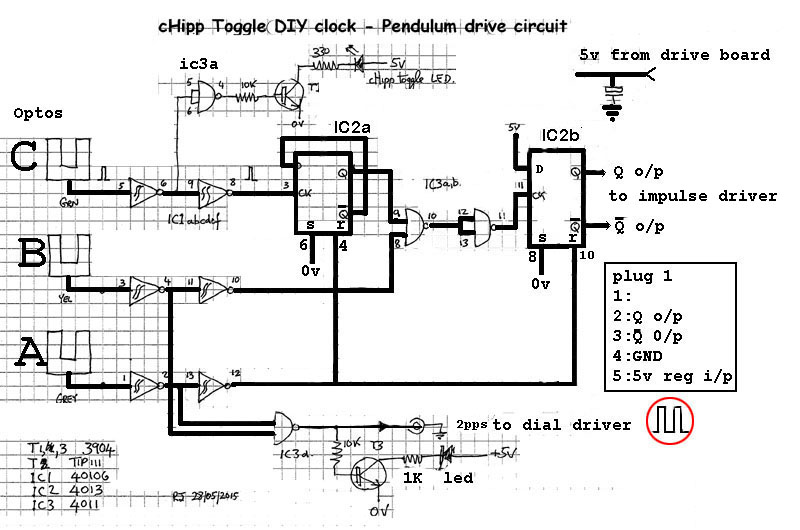
The purpose of Ic1 (6x Schmidt trigger inverters) is to speed up the pulse edge transitions from the opto-isolators. Used in pairs, the original pulse polarity is maintained.
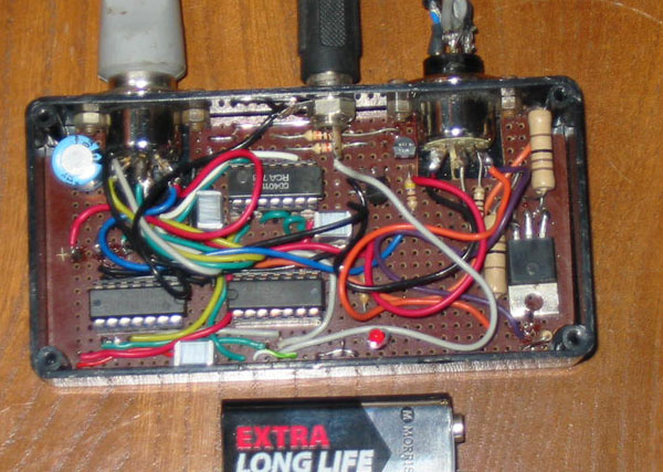
The completed electronic cHipp Toggle unit. You can probably do better with a PCB.
![]()
We now have a drive pulse positioned 1/4" either side of BDC which, when amplified by the transistor switch, powers the EMs for 220 milliseconds; that period being set by the distance between opto A and B.
![]()
Frank Hope Jones in the Synchronome clock, powered his pendulum at fixed 30 sec intervals with the potential energy of a gravity lever hanging up on a catch so that the energy imparted as the bob passes through BDC was always the same.
The pendulum impulse in this clock is delivered magnetically to the armature beneath the bob. The force of attraction of a magnet varies as an inverse square law of the decreasing distance to the approaching armature. The actual force is the resultant of sideways and downward attraction. (Downward attraction increases the apparent gravitational force which also accelerates the clock)
In this clock, the energy that pulses the
EMs does not come directly from the battery, but from a capacitor
charged to precisely 5 volts from a voltage regulator. This ensures
that the same energy is available on every impulse. The capacitor
value was found by trial and error to empty its charge during the
220 millisecond period that the drive is energised. Because of the
capacitor the current through the EMs decreases exponentially over
the 220 millisecond drive period.
Without the capacitor, as the distance to the EM decreases, the
effect of the magnetic attraction would increase as the square
law. However the magnetic field is decaying exponentially due to the
discharging capacitor and (it is hoped) the two effects will produce
a roughly steady and gentle accelerating force on the bob.
The oscilloscope image below shows the falling voltage applied across the drive coils during the 220 milliseconds pendulum drive period. A side effect of this system is there is virtually no back EMF generated when the switching period ends, so protection of the switching transistor is not needed.
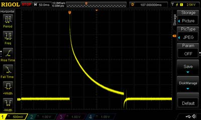
The armature beneath the pendulum is of low remnance steel taken from a GPO relay. There are no fixed magnets in this design. (and no auxiliary timing circuits)
Here is the circuit diagram of this
"capacitor drive" section.
(this is a scan of my own notes so the pin numbers etc are not
relevant)
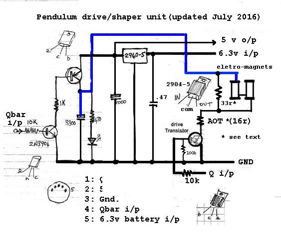
How it works. The Q-bar output of ic2b in the Hipp toggle circuit , which is normally HIGH, is connected to the input (i/p) on the left. This turns on 2n3906 transistor which in turn turns on the 2n5193 PNP transistor above. The 3300uf capacitor is charged quickly to 5 volts exactly . The 5 volts comes from the 2940-5 low drop out voltage regulator (2940-5).
When the cHipp Toggle circuit calls for a pendulum impulse, Q of ic2b turns on the EM's drive transistor (lower right), At the same instant Q-bar goes low , removing the 5 volt feed to the 3300uf capacitor. The capacitor is now the only source of current for the EMs during the drive pulse period. (220 Milliseconds)
* the 16ohm and 33ohm resistors in the electro-magnet circuit were adjusted to achieve a time between impulses of about 30 seconds. Later the period was changed to over 50 seconds.
![]()
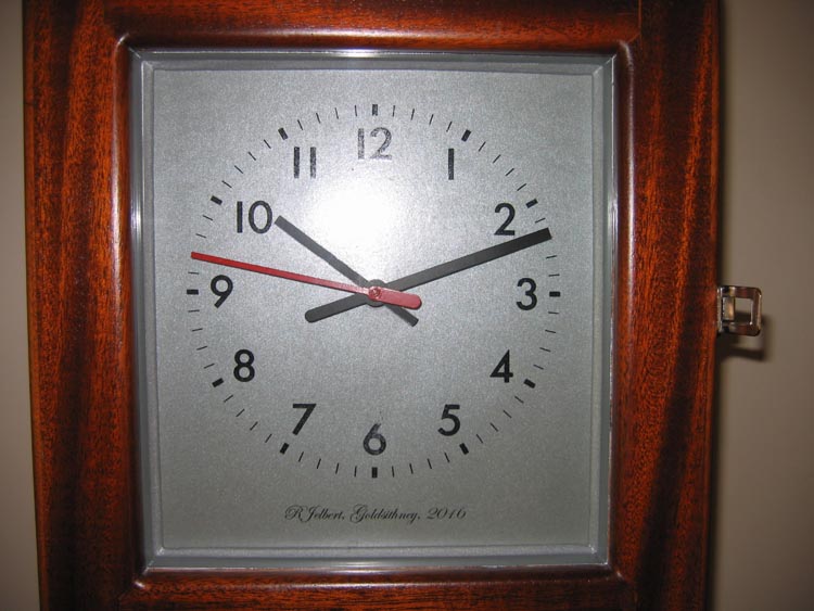
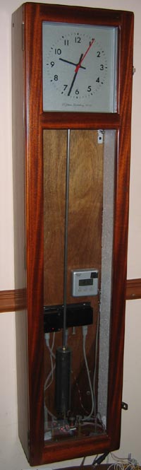 The clock |
The pendulum rod
comprises a 1 metre length of 8mm Invar, extended with a
short length of steel 4Ba studding to make up the required
length and to carry the rating nut. The pendulum's arc of swing is determined almost entirely by the spacing of the opto-interupters and is, on average, just 1.9 degrees. (.95 semi-arc) The pendulum is about a "free" as a pendulum can
be without being enclosed in a low pressure tank. (as in the
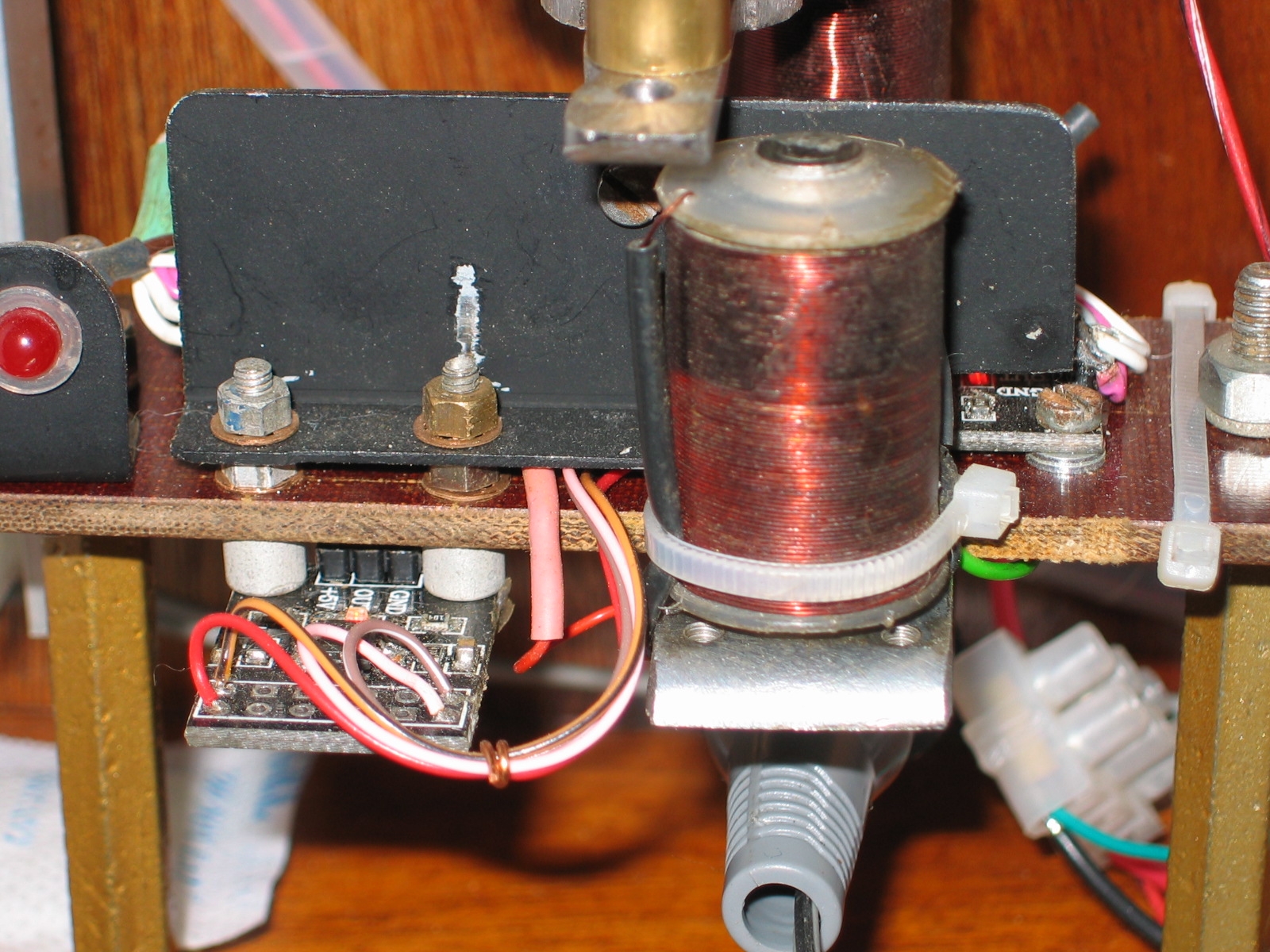
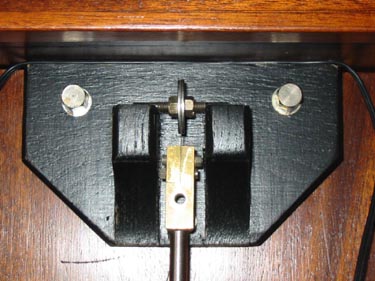
Shortt / Synchronome clock) The pendulum is suspended on an oak bracket and the top chops are similar to those used by Gents and the GPO No.36 clock – two penny washers and a length of threaded rod. A piece of .005” feeler gauge stock serves as the suspension spring. The pendulum bob is steel and measures 2" x 8" The picture below (left) shows the pendulum stationary at BDC and the magnet drive assembly. The the optos interrupters are behind the black plate, The electro magnets were taken from an old buzzer. In spite of the small black shields, direct sunlight falling on the clock can upset the operation of the opto-isolators, therefore the clock needs to be positioned where the sun cannot directly shine on it. The dial mechanism is a Gents 1 second, alternate polarity unit with a silver effect dial card printed on a PC printer.
|
 |
 |
|
Drive magnets and optos behind the plate
|
Oak pendulum support and chops
|
The cHipp Toggle clock has no friction other than that of the suspension spring and the air through which it passes. It has a very small arc which is tightly controlled so circular error has virtually no impact. The is no escapement to interfere with the motion of the pendulum except for the precisely controlled impulse which are now every 50 seconds. Reasonable temperature stability is achieved with the Invar rod and a bottom supported bob expanding upwards. Therefore I am tempted to believe that an electrically impulsed clock of this type might be as good a pendulum clock as can be constructed whilst running in free air. A carbon fiber rod might be a cheaper alternative to Invar but I haven't tried it.
It was Frank Hope-Jones's Synchronome clock system (and his previously mentioned book) that inspired me to make this clock. One of the advantages of the Synchronome system is that the current consumption of a Synchronome clock is miniscule whereas any electronic clock has a continuous drain. Of course, in a modern quartz clock this drain is reduced to a tiny current but the cHipp toggle clock is drawing 90 Ma continuously because of the three opto-isolators, LEDS indicators and the electronics.
This is not much of a problem as I've used a trickle charged 6 volt lead acid battery in case of a power cut.
Originally the clock was fitted with a Synchronome dial mechanism that required an impulse every 30 seconds. This was taken from opto B and a CMOS divider circuit was included to make the impulse every 30 seconds. This has now been dispensed with and it's now fitted with the Gents, silent, seconds indicating, alternate polarity slave clock mechanism mentioned in the introduction. The dial motor resistance is 3.4 ohms and the required drive current is 220Ma. The dial was printed on silver card with a laser printer.
Pulses from optos A and B are "OR'd" and inverted in ic3d (circuit above) and fed to the circuit below.
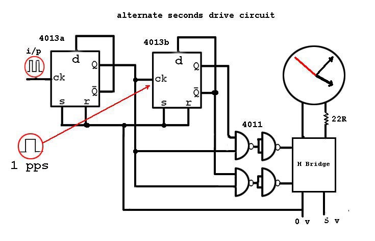
Alternating polarity pulse driver for the Gents low voltage,
silent dial mechanism.
The incoming double pulse is converted to a single pulse of about 220 milliseconds duration with a period of one second by 4013a (ic3a). This is divided by 2 in 4013b. The two opposite phase (Q & Q-bar) phase outputs are gated with the single pulse to produce positive going pulses of 220 milliseconds duration alternately, to drive the H-bridge. It was just luck that the spacing of Optos A & B were 220 Milliseconds apart and that the pulse resulting at 4013b i/p was a suitable length to drive the Gents dial movement.
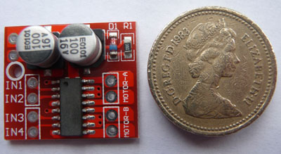
H-bridge module with one pound coin.
The gem in this circuit is the tiny H-Bridge module sourced from eBay for a mere 99p post paid. Rated up to 10 volts and 1.5 amps its more than adequate to drive the dial motor. Pictured above with a £1 coin for scale, it features two H-bridges, so a couple of additional series dials could be run separately from the B output.
The steady current consumption is now 100ma - mostly due to the LEDs in the Opto-interupters and the other indicators.
![]()
How well does it work ?
It has met the original aim of equalling the time keeping of a
Synchronome ie. within 2 seconds a week. But the effect of changes
in barometric pressure are obvious - as in any pendulum clock with
pretentions of accuracy. Unless barometric compensation is
incorporated, variations during a week's trial can be extremely
variable. Therefore after the initial rating adjustments are done
nothing should be touched for a whole week. Then the error should be
assessed with an eye on what changes have occurred to the pressure.
The ultimate solution is to enclose the pendulum in a low vacuum
enclosure, as in the Shortt/Synchronome clock.
![]()
The construction of the clock has been an on/off process over several years. During that time I've been lucky enough to make the acquaintance (online) of a chap who has written a program for the Raspberry-Pi (mini computer) that can monitor and record the going of a clock in remarkable detail. Originally designed for the Synchronome system it accepts and records the timing of the 30 second pulses against internet time (NTP) I've used a divide by 30 board which formed part of my clock in its first configuration to feed the Pi monitoring system.
![]()
And now another clock but not a Hipp Toggle.
In 1842 when Hipp thought up his Toggle it no doubt served a
valuable purpose as early current sources were variable and
unreliable. Now, with stabilised power supplies and trickle charged
cells the supply voltage to a clock can be absolutely constant. Once
adjusted the cHipp Toggle clock does not vary from 50seconds between
impulses that I settled on, so arguably, the Hipp Toggle action is
not actually required. A clock built on the same principle as the
Synchronome, with drive pulses every 30 secs is likely to be equally
stable. The Synchronome timing element is a 15 tooth count wheel. If
this function was to be provided by an electronic counter the
pendulum would be completely detached and, like my Hipp Toggle
clock, would only require an impulse at even more infrequent
intervals. In fact, an unloaded pendulum will easily swing
satisfactorily with a drive pulse every 60 seconds - and probably
more.
The clock I will describe now came about as a result of an email from a mechanical engineer who enquired about an electronic drive system for a clock he had constructed. In his clock the pendulum drove the the clock mechanism via a pawl attached to the pendulum. I agreed to assist with a doable plan - and I decided to make a wholly electronic version at the same time.
![]()
Both clocks have a 1 metre pendulum so we needed to count the seconds. I choose as a basis an cheap electronic timer kit available from eBay for about £3. Search "2 digit timer kit" Click HERE to read more about this project.
Updated July 2020
The cHipp Toggle clock is no longer a work in
progress. It has worked well for several years.
***
what is sound mixing