![]()
![]()
![]()
| A DIY electronic pendulum clock. This page is a work in progress
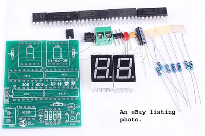
This clock is impulsed at fixed intervals exactly like the Synchonome and many other master clocks. The Synchronomes impulse every 30 seconds and the majority of dial mechanisms available secondhand are therefore 30sec steppers. However with no load at all on the pendulum, one pulse per minute is easily possible. I could have made a suspended pendulum from scratch but I had some spare parts of a Magneta clock which is almost the same as the popular PO 36. Indeed this drive system could be applied to a PO 36 without damaging it permanently. This is a very simple project with the electronics being based on readily and cheaply available from Chinese suppliers on eBay. The main module; the electronics that replaces the count wheel, is usually listed as"2-Digit-30-60S-Counter-Timer-Simple-Stopwatch-Digital-Electronic-DIY-Kit" The number of suppliers seems to vary and the price is about £3.
As supplied, the kit is a simple (not very accurate) timer for either 30 or 60 seconds, selectable by the 30s/60s jumper on the left. The 555 timer is wired as an astable oscillator. With a simple modification the 555 can be changed to a monostable with an "on" time of about 30 seconds (using the components supplied in the kit.) This timing can be adjusted by changing R7 to suit the clock drive requirements but I'm using the standard values. The
input to the counter will now be a sensor which detects the passes of
the pendulum. The
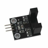
passes of the swinging pendulum are sensed with the same opto-switches
used in the Hipp Toggle clock. Still widely available on eBay listed
as" LM393 Speed Measuring Sensor Photoelectric Infrared Count
Sensor DC 5V W2O4" or similar. Be careful though - there are
dozens of listings for similar devices with a much narrower slot. The
ones I have used have 10mm between the sensing pillars. It would be
very difficult to stop "flag" hitting the sensor pillars when
the slot is much narrower.
The
"flag" in my case is a short length wire about 1.6mm diameter,
projecting from the pendulum rod and bent down at a right angle to pass
through the sensor arms. The sensor coprises an infra-red transmitter
in one arm and am IR diode in the other, An onboard opamp (comparator,
the LM393) snaps from low to high when the beam is interupted to give
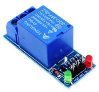
a full voltage high signal. The output pulse leaving the 555 monostable could feed a medium NPN power transistor to switch the clock's electro-magnet or a cheap single channel 5volt relay module.
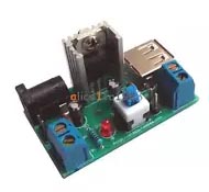
The whole system was powered by a 12volt 1amp power supply from an old broadband router with this linear regulator proving 5volts for the counter, the sensor and the relay.
My original plan was to set up the counter for 60 seconds and use a 60 sec stepper dial I already had. But that slave movement was too deep to fit the clock case and I had to revert to using a standard 30 sec Synchronome slave. But the counter is eminently modifiable and so it was decided to stay with 60 secs between impulses and pick off 30 secs impulses to drive the slave. This allows the 2 digit display to remain as a viewable part of the time display, ie. in lieu of a seconds hand.
Unlike a count wheel, the counter does not know in which direction the pendulum is passing therefore it must be started with a right to left push. (or press the zero button when it is to the right of the sensor) If the counter ever misses a count or receives a spurious additional count it will impulse the drive when travelling in the wrong direction, causing the clock to stop. In practice this has not happened but If the sensor is mounted off centre the digital display will show an irregulat count, ie. 1*2****3*4 etc. and that can used in an additional circuit to correct this if it ever becomes neccessary. This placement also allows for a good long gentle drive pulse.
Here is the circuit diagram of the counter as supplied. Click it to download a high resolution version.
Here is the circuit diagram after modifications. Click it to download a high resolution version.
As supplied, the 3rd & 4th gate in the 4011 are spare and not connected to anything (bad practice - the inputs should have been tied to Gnd.) Optionaly, these spare gates can be wired to provide counts other than the 30 & 60. This was a requirement for the mechanical clock which needed the 20sec impulses on pin 11. The output on pin 10 is not specified but can be set to counts below 20 depending on which pin of U3B pin 8 is connected to. The output of the choosen gate is fed directly to pin 2 of the 555 (the i/p) where the negative going transition will trigger the output pulse. Note that the output of the 555 is also used to Reset the counter to 00. This proved less liable to interference than taking the Reset direct from the transitent pulse from the 4011 in use. The tracks to S1 are all cut close to the solder joints and the the 3 pin header is used as an i/p - o/p connector. In my version I drilled an extra hole and used a 4 pin header because of the additional output. *R4. R4 is not used as originally intended, so after cutting the track to the "hot" side the space on the board is used to accept the group of components shown which tame the input pulse from the opto sensor. I have tried other types of sensor including opto relective and magnetic but none have prooved to be so easy to set up as the type shown. These come with a comparator on a tiny pcb but the design of the comparator is basic. It does not include any husterisis and the result in the examples I've had is that the transistions are accompanied by a short burst of instability - HF oscillations. This could be fixed with an additional 555 monstable "de-bouncer" but I found by trial and error that the three components shown do the job. Without them, the counter would advance by a random number of counts each time. U3, the 4518, is tolerant of slow rise time inputs which helped a lot in overcoming that counting issue. With the modification to U3B, pin 10 wired to VCC, it accepts +ve going inputs on pin 9. However is a different i/p sensor was used a -ve going input pulse could be accomodated by using pin 10 as the i/p and wiring pin 11 to GND. All wiring mods to the track side of the board were done with the thinest insulated wire I could find. I believe it was "wire-wrap" wire and had n overall diameter of only 0.47 mm and was single strand. A step by step guide to the tracks cuts and wiring mods will be available for download asap..
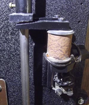
A few words about the drive magnets of the PO Type 36 clock.
I make no claim to be an expert horologist so feel free to disagree with what follows. The drive magnets of the cHipp Toggle clock were positioned below the bob as per the several old publications on DIY electric clocks. The timing and duration of the drive pulse applied that case is quite critical but the PO36 system (pictured) is much more tolerant. The drive apears to be delivered to the pendulum as a downward force (ie an increase in apparent gravity) and my experience is that the timing and duration of the electrical impuse is far less critical. My clock worked well with the R5 & C1 components supplied in the kit which gave an "on" time of about 0.5 second. |
||
*** The end *** |
||