
![]()
![]()
The Philips TD1316AS-IVP is available on the Internet from a variety of sources for a very low price. Unfortunately, accurate Tuner data sheets are next to impossible to find on the Internet. Some datasheets for the Tuner and the tuner-IC used exist, however. The TD1300 datasheet made available from the vendor is not applicable to this model of tuner and is only partially useful for the hobbyist. This tuner can be used to build all kinds of radio communications devices including spectrum analyzer applications. Controlled by a small micro computer and by the addition of a suitable IF Amplifier a complete VHF/UHF receiver can be built. To help the hobbyist some information on the work done is shared here.
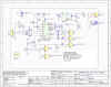
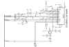
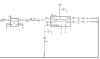
Below are some of the results from some investigative work done, allowing to actually get the tuner to work for the hobbyist. An existing micro computer was used to program the tuner IC TUA6034. The schematic shown below was used to test the tuner operation and performance.
Comments:
| This tuner operates on a single 5V supply and generates its own 33V PLL Tuning voltage | |
| Narrow Band IF Output has little filtering | |
| OFDM IF Output has SAW Filtered output | |
| Maximum Gain as measured is about 50dB | |
| Frequency Range is about 50 to 850MHz. | |
| PLL Lock Monitoring Bit | |
| Analog I2C address sub-selection using TUA6034T AS selection pin. | |
| I2C Base address is 0xCn, where n denotes the sub address selection via the AS input (pin7) |
| TDA1316AS-IVP Tuner Application Information (PDF Format) |
 |
 |
 |
TD1300
Series Tuner Datasheet |
| Tuner
IC Information (PDF Format) |
TUA6034 Data Sheet Ver 2.51 |
App
Note TUA6034 Part 1 |
App
Note TUA6034 Part 2 |
App
Note TUA6034 Part 1 |
TD1316AS-IVP Tuner Connections as discovered
| Pin Number | Pin Name | Comments |
| 1 | TBD | Not sure what it is for |
| 2 | +5V RF Section | This pin is used to supply DC supply voltage to the RF Gain block |
| 3 | n/c | |
| 4 | n/c | |
| 5 | RF-Gain Control | 0-4V applied to this pin allows wide range gain control |
| 6 | Vtun Out | PLL Tuning Voltage Monitoring Point (0-33V) |
| 7 | Adress Selection | TUA6034T Analog I2C address selection input |
| 8 | SCL | I2C Clock Input |
| 9 | SDA | I2C Data Bus (input/Output) |
| 10 | 4 MHz Output | 4 MHz PLL Reference Oscillator Output |
| 11 | +5V Tuner Section | TUA6034T Supply Voltage |
| 12 | Narrowband IF Out | Analog IF Output - Not much filtered |
| 13 | IF Gain Control | COFDM Gain Control input (0-4V), 75 Ohm load |
| 14 | Wideband IF Out 1 | COFDM IF Output 1 (0 Degrees), 75 Ohm load |
| 15 | Wideband IF Out 2 | COFDM IF Output 2 (180 Degrees ) (Differential Output) |
For the following please refer also to the TUA6034T Infineon Datasheet
The tuner IC TUA6034 has a base address of 0XCn, where n denotes the sub address selected via As pin 3 or Tuner Pin 7. The tuner provides external access to the AS I2C address selection input. This pin allows to select up to 4 sub addresses:
| AS Pin Voltage Level | MA1 | MA0 | I2C Write Adr. |
I2C Read Adr. |
Comments |
| (0 to 0.1) x Vcc | 0 | 0 | 0xC0 | 0xC1 | Ground Pin |
| open circuit (0.2 to 0.3) X Vcc | 0 | 1 | 0xC2 | 0xC3 | Leave open circuit |
| (0.4 to 0.6) x Vcc | 1 | 0 | 0xC4 | 0xC5 | Use 10K resistor divider to provide 2.5V |
| (0.9 to 1) x Vcc | 1 | 1 | 0xC6 | 0xC7 | Connect to Supply Voltage |
To select the final address connect Tuner pin 7 as shown in table above and make sure the voltage measured on this pin conforms to the equations listed.
The TUA6034T used in this tuner utilizes a I2C communications interface for control and monitoring. The protocol used is very simple and only 5 data registers are required for operation of the tuner. The registers used are shown in the data sheet on page 50, Table 8.
Please note that the tuner on read operation only returns the status byte. The data registers cannot be read back.
The function below was used for testing the tuner with a PIC18F4620 and the CCS compiler. This example is intended to demonstrate how to communicate with the tuner in the most basic form.
void query_TUA6034T(int adr)
{
i2c_start();
i2c_write(adr);
i2c_write(_ioregs[10]); // DB1
i2c_write(_ioregs[11]); // DB2
i2c_write(_ioregs[12]); // CB, 50KHZ, 250uA,
i2c_write(_ioregs[13]); // BB or AB, LOW BAND ACTIVE
i2c_stop();
delay_us(80); // Controller must wait 60us to allow PLL to settle.
// Read Status Byte
i2c_start();
i2c_write(adr+1);
_ioregs[17] = i2c_read(1);
i2c_stop();
}
For this test DB1=0x06, DB2=0xB8, CB=0xC0, BB=0x01 ; adr = 0xC0 (with AS grounded)
F[PLL] = 86.000MHZ
F[REF] = 50khz
F[IF] = 36MHZ
Tuner Inp = 50.000 MHz
Status byte return in register 17: Locked=0x70, unlocked = 0x30
To Calculate N: N = (Finp + Fif) / Fref ; For Example:
Fin = 85MHz, N = ( 50 + 36 ) / 0.05 = 1720
(under construction - More info to follow)
All Information is provided as is. All risks lie with the user. No responsibility and liability are assumed for the use of the information and resources embodied here.
© Copyright 2002-2011